Adpt-X3-M1P16
Overview
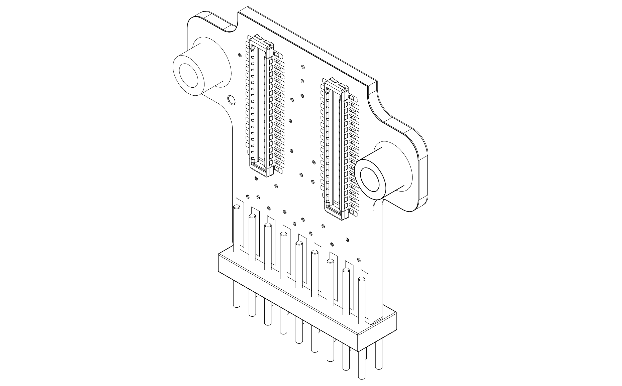
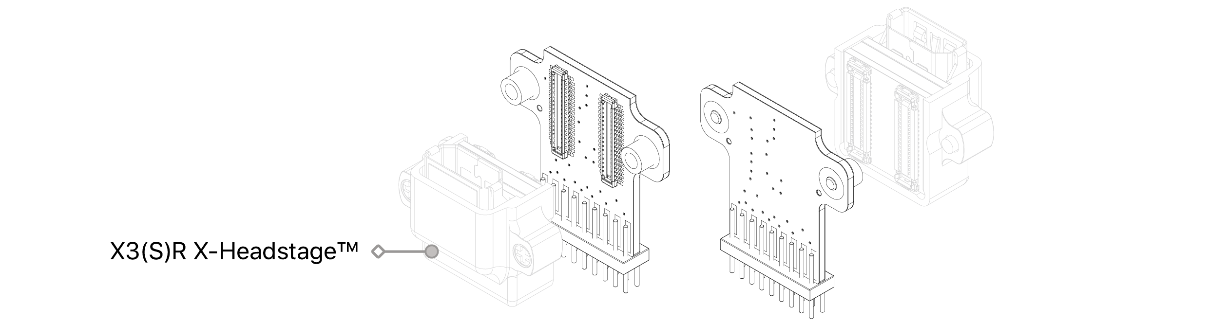
The X3 Adapter to Pin Header 16ch is designed to facilitate connectivity between X3 headstages and 16-channel electrode interface boards (EIBs) equipped with 1mm socket pin headers. This adapter is compatible with X3SR16 headstages.
Adpt-X3-M1P16 Overview
Connector
- Molex PN: 505070-3422
- 1.00mm_Pin Header_18P(2x9)
Headstage
Probe
Dimension
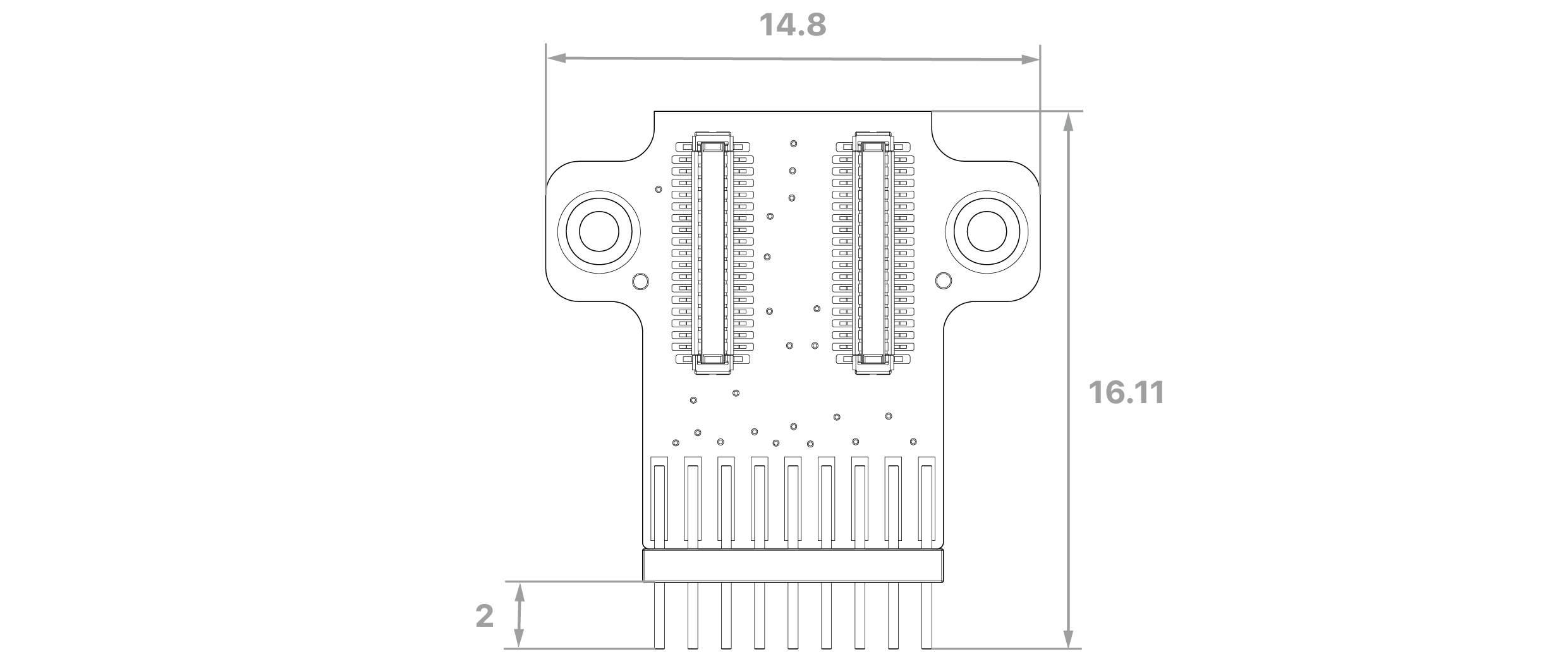
unit: mm
Key Features
Universal Compatibility
Supports all X3 headstage configurations (X3R and X3SR).
Pin Header Interface
Connects seamlessly to 16-channel EIBs featuring 1mm socket connectors.
Compact Design
Maintains a small footprint for space-constrained setups.
Versions
V1: Identified by PCB marking '100094' or by the blue board color when the marking is absent.
original design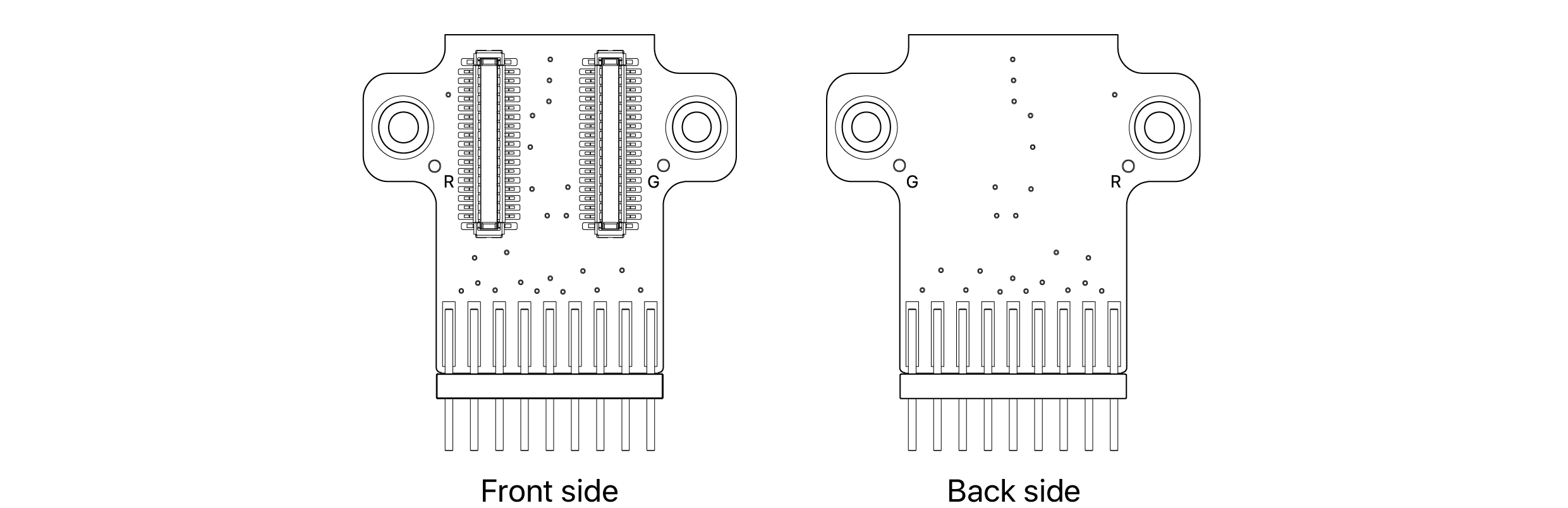
V1.1: Identified by 100094A on PCB
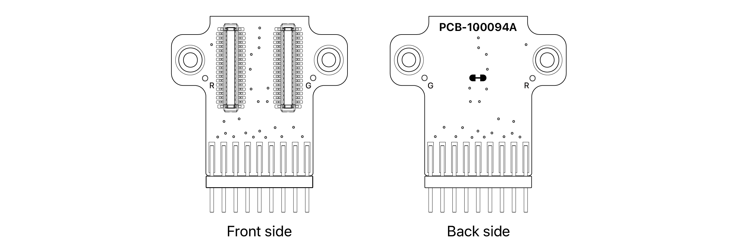
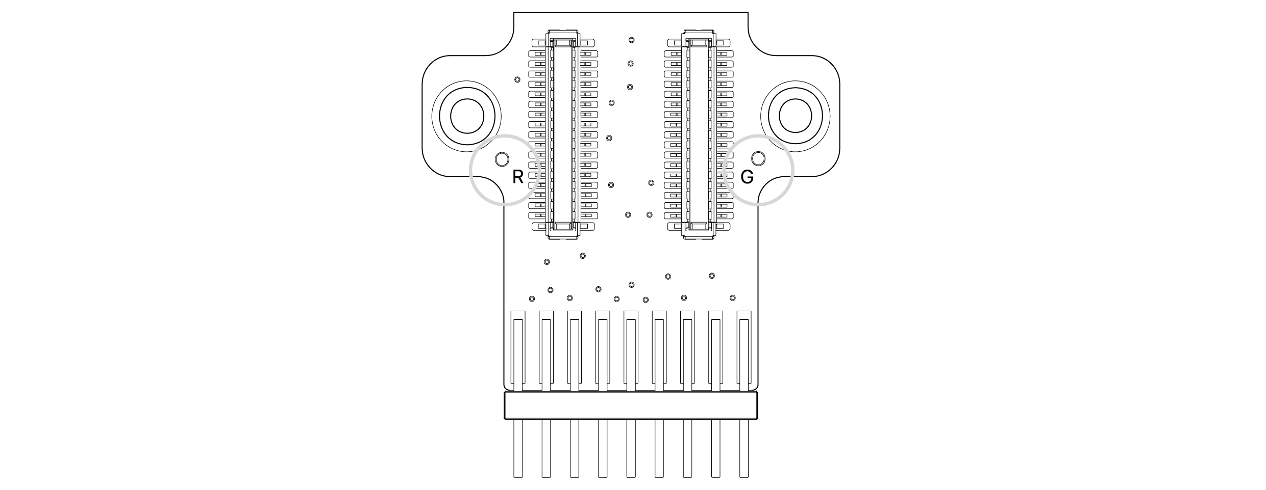
Ground & Reference Configuration
Adpt-X3-M1P16
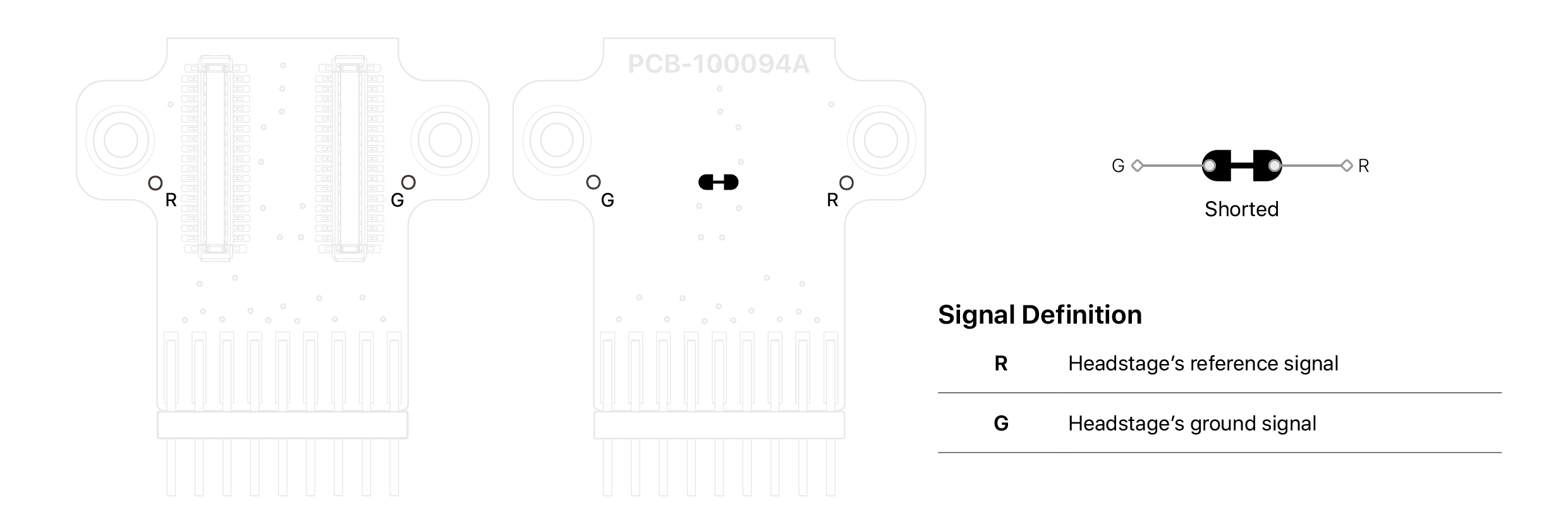
- Ground (G) and reference (R) signals are independent by default.
- To short them together at the adapter, solder a short wire between the G and R pads.
Adpt-X3-M1P16 v1.1
Proper grounding and referencing are essential for high-quality signal acquisition. Always ensure that both ground and reference signals are securely connected. If either is left floating, significant noise may be introduced into the recordings.
Configuring the Jumper Pad
① To connect the jumper, apply solder around JP1 until a solid solder bead forms.

② To disconnect, use a soldering iron and desoldering mesh to remove the solder bridging the jumper pad.
If the jumper pas has a default short configuration, use a scalpel or precision blade to cleanly sever the trace.
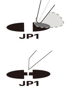
③ After modification, clean the area thoroughly using isopropyl alcohol or flux remover to eliminate any residual material.
④ Always verify connectivity using a multimeter to ensure proper configuration.
④ Always verify connectivity using a multimeter to ensure proper configuration.
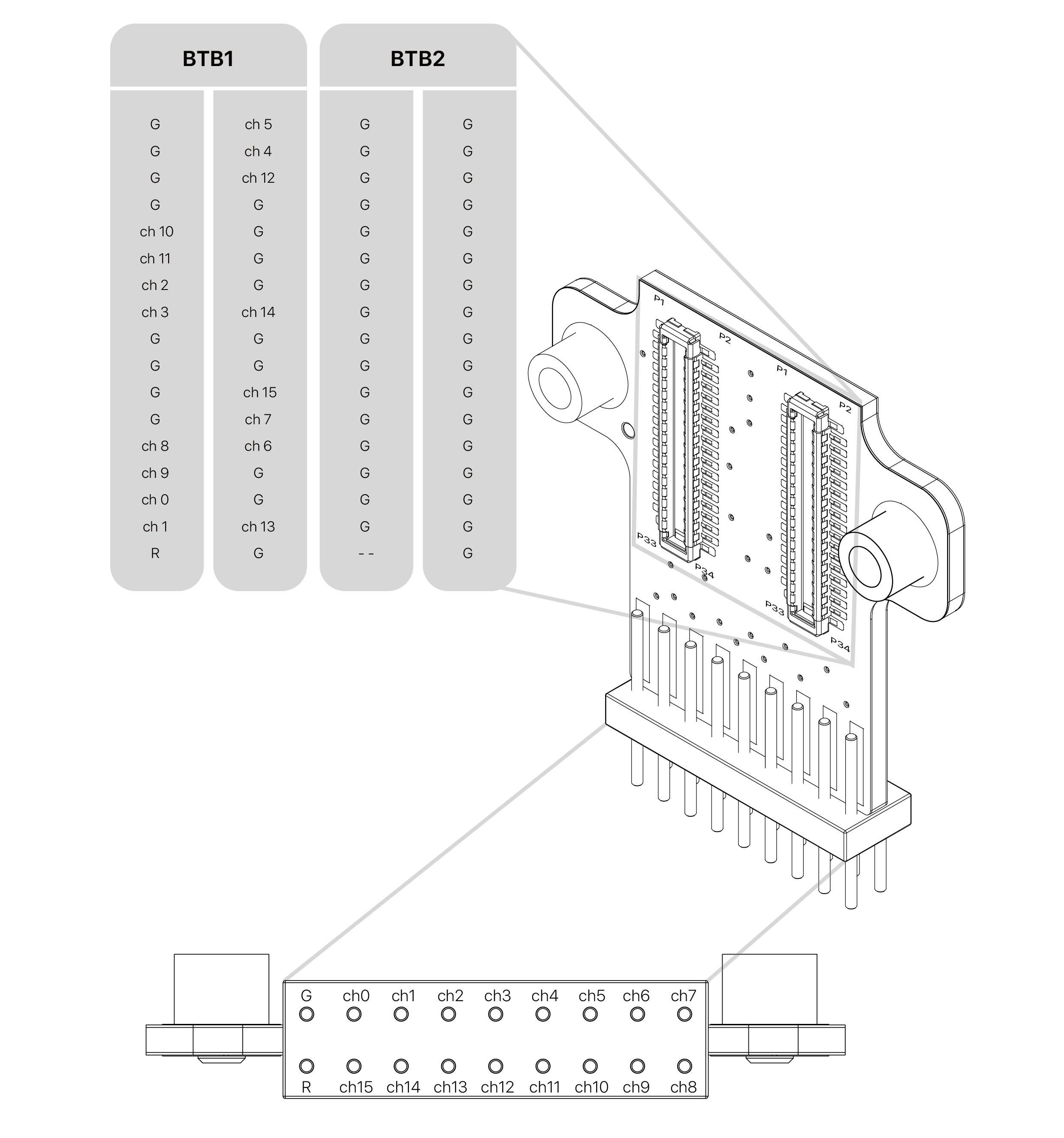
Pin Map
V1: Identified by PCB marking '100094' or by the blue board color when the marking is absent.
original design
V1.1: Identified by 100094A on PCB
![]()